Building and troubleshooting the D-LA2A dual optical levelling amplifier
| November 3rd, 2012Early this year we scrounged together the cash to get the parts to build a D-LA2A, a very clever and well-documented project where you can make a pair of LA2As on a single printed circuit board.
The LA2A, if you’ve never encountered one, is a circa-1965 compressor or levelling amplifier. It’s one of those classic pieces that never really fell out of favour in pro audio circles. It only has two knobs (gain and peak reduction) and it’s pretty much impossible to get a bad sound out of it.
If you’re not familiar with audio compressors, they’re basically devices designed to lessen the differences between loud and soft audio signals, smoothing out erratic dynamic shifts. The LA2A’s is historically significant because it was the first truly effective ‘optical’ compressor, meaning it controls gain through electroluminescence and photo-resistance. As the audio signal intensifies, an electroluminescent panel glows; this in turn causes a coupled photo-resistive circuit to trigger gain reduction.
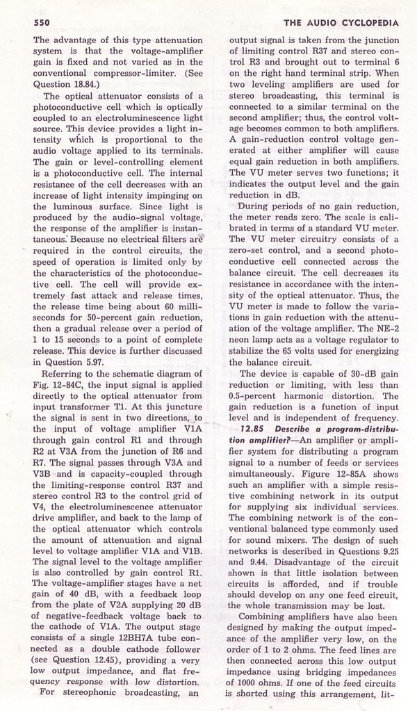
My description is horribly crude, so I scanned these pages from the Audio Cyclopedia by Howard Tremaine, which explains the LA2a’s workings clearly and accurately (click them to enlarge); for LA2A aficionados like us, discovering this document evokes Young Frankenstein: 
The LA2A as explained by smart people
For the truly curious, a person named Christian Sugar created this very nice circuit deconstruction:
Twin peak reduction: the making of a sequel
We’d already built a single LA2A clone in a 3RU chassis using a Drip Electronics PCB a year earlier, and we’ve used it on pretty much every session since. When we read about the DLA2A we were pretty impressed that that Volker, the German fellow who designed the circuit board, was able to squeeze the two of these comps onto a single compact board without compromising anything. And as a bonus, LA2As work quite well stereo-linked as bus compressors.
We decided to go for it and ordered everything so they’d arrive in time for the Christmas holidays. The Printed circuit board and a custom toroidal power transformer came from the guy in Germany who thought the whole thing up [Silent:Arts] (he’s a classy fellow, the package only took about a week to ship from overseas and he tossed in some gummy bears); we got the audio transformers from Edcor in USA (which are much cheaper than the British Sowter transformers we used for the Drip LA2a); the tubes were from thetubestore.com in Hamilton; we found a Par-Metal aluminum chassis on eBay; we got stereo-matched T4B opto-attenuator units from Drip in Santa Fe; the rest of the parts were either from a local surplus shop or Mouser Electronics in Texas (we’re kinda glossing over this: prepare for hours of staring at catalog pages on computer screen to order all the resistors, capacitors and other bits and bobs—it’s the second most annoying part of all this DIY electronics stuff, next to only the dreaded metalwork).
The first sines of trouble or Doctor, it hertz when I do this
The build was quick and straightforward. It only took a day-or-so (except for the metalwork–that was annoying and tedious and we have no real aptitude for it) and everything worked from the first power up. There was only one bug–at very high gain levels it would self-oscillate. Even though it didn’t interfere with normal usage (it would only oscillate at impractically high levels) this still really stuck in our craws. We needed to do something about it.
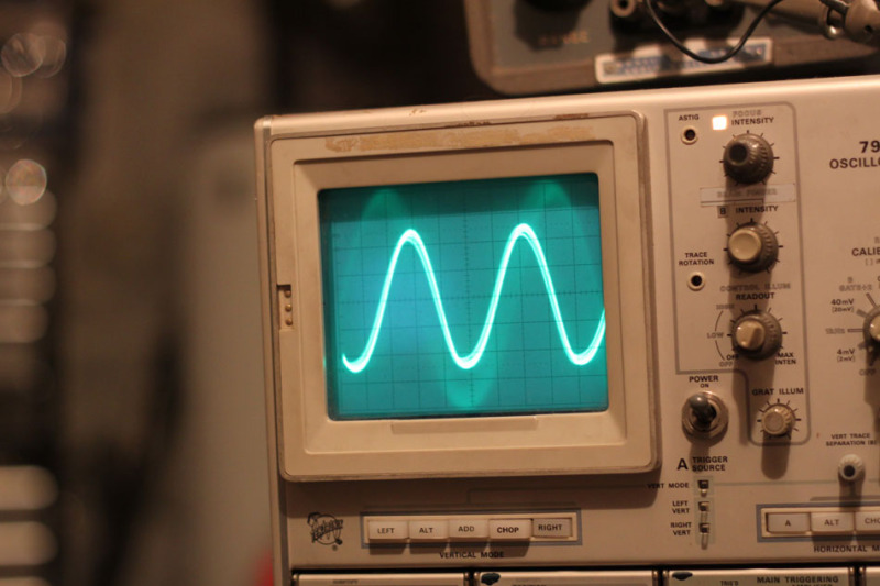
To begin troubleshooting, we checked it out with the ‘scope. As the pic below shows, it was pretty clean sine wave at 30Khz. Lacking much in the way of repair know-how, this didn’t really tell us anything that we could act upon. It did, however, allow us to take a picture of a nice ‘m’ shape.
In keeping with our astoundingly foolish troubleshooting ways, we decided to change a bunch of things at the same time. This assured us that even if we set things right, we’d never know for sure exactly what fixed it.
The first thing we did was add a socket to C4, the capacitor that governs the high frequency response. This let us choose the precise cap value to get us a flat response up to 20KHz without allowing too much ultrasonic (>20KHz) signal to pass through (which could contribute to that oscillation). It turned out that we had to use different values for the two channels to get them to match exactly (100pF and 250pF).
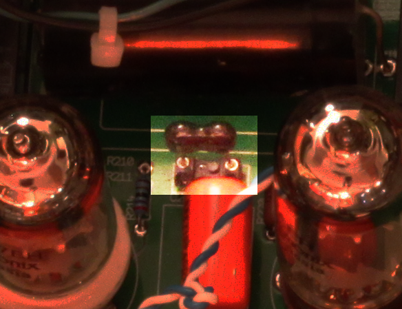
We decided to add a socket for C104/C204 (C4 in the original LA2A schematic). This capacitor plays a large part in determining the frequency response.
Next, we completely re-wired the whole thing. Lead dressing is a black art to us. We had the leads fairly long intially so that we could run them far away from any hum-inducing parts. With the re-wiring, we decided to go the route of keeping the wire lengths as short as possible (our theory being, there’s less surface area for interference to creep in). Once again, thanks to our lunkheaded and impatient try-a-bunch-of-things-at-the-same-time troubleshooting ways, we’ll never know 100% for sure if this made any difference. It did at least seem to lower the noise floor a bit.
Along the same lines, we also set about rearranging the audio transformers. Previously, they were tidily and symmetrically laid out. We changed them so they’re as far away from each other as we could fit. We used bolts stuck to the chassis with JB Weld for mounting. (Aside: JB Weld is good stuff–Freelove Fenner would totally be up for writing a jingle for the company. If you’re reading this JB Weld person, let’s talk turkey).
Another minor change we made was to remove the neon bulbs that are used for regulating the gain reduction metering and replace them with zener diodes. The zeners are allegedly quieter and more stable.
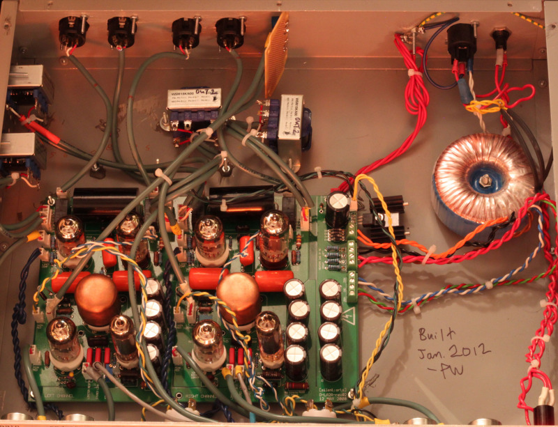
Here’s the innards of our D-LA2A. They had been a little bit tidier before but we shortened nearly all the leads in the course of troubleshooting the oscillation issue; the veroboard in the back is just there because we accidentally bought PCB mount pots for the zero set.
The last major change we made was modifying the circuit to use 12AY7 tubes rather than 12AX7s in the V1 position. This lowered the maximum gain slightly, but the AY7s are nicer sounding (subjectively, natch) and less trouble-prone tubes. This required a few resistor changes in the circuit. This was all first suggested by a knowledgeable fellow named CJ in California.
The good news is that all these changes (or one of these changes−who knows?) worked! Our D-LA2A is now quieter and completely immune to self-oscillation. Shown below are a few pictures of our build.
Topless pics:
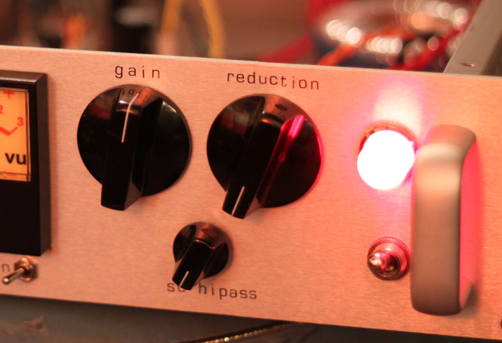
Channel 2 controls in detail. We used Davies Molding phenolic knobs. The truly observant might notice the third knob, not present in the original: this is the side-chain high pass filter which is an internal adjustment on the real ones (intended to make the unit more sensitive to high frequency peaks, for protecting FM transmitters from overmodulating). We find it handy for bus compression duties (less ‘pumping’ from bass).
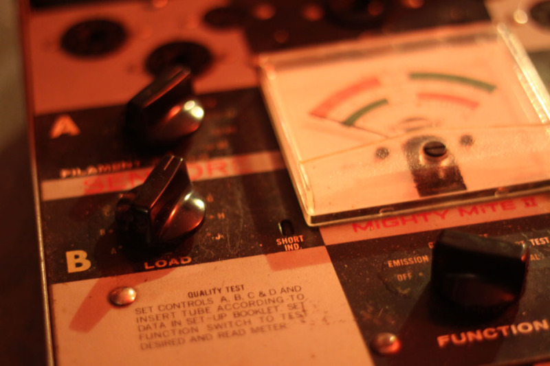
Mighty Mite II Tube Tester. This is from about 1960. We were surprised that Davies Molding is still in business and still selling the exact same phenolic knobs on this guy.

We used a Neutrik Powercon connector for the AC inlet rather than an IEC. They’re way easier to install because they only require drilling a circular hole, rather than the annoying square hole for IECs.



![The [Silent:Arts] D-LA2A printed circuit board](http://www.diyrecordingequipment.com/wp-content/uploads/2010/09/DLA2A-rev02-Top-grn.jpg)


 |
|
Wow ,I love old tube stuff ,just finished a sixteen channel limiter/compressor for my tascam MSR16 DolbyS to get more drive and crisp on the tapes .Offcourse NOS tubes and the best caps ,attack and release I see at my livecompressors BSS and Drawmer working for more than thirty years .Katodefollower is the output ,the optical resistor in the feedback from anode to grid and working very fine with a white LED .Have fun …..